

A deck project in West Jordan can look straightforward until the cable railing takeoff begins. A homeowner measures the run, places posts at attractive intervals, and orders cable by the approximate length. Then the finished guard moves under pressure, the openings look too wide, or the inspector asks for a system-specific layout that the original material list never accounted for.
Cable railing post spacing isn't only a visual decision. It controls cable deflection, post loading, corner transitions, stair geometry, and the amount of terminal hardware required. A reliable layout starts with the completed guard assembly and the selected manufacturer's instructions, not with a universal spacing number copied from another deck.
Why Post Spacing Dictates Your Entire Railing System
A cable guard is a tensioned, load-sensitive assembly. End posts and corner posts receive the accumulated pull from multiple cable runs, while intermediate posts shorten the unsupported distance where a person can push against the cables. If those intermediate supports are omitted, the cables may move enough to enlarge the clear opening even when the original layout looked precise.
The foundational U.S. code milestone is the 2015 International Building Code and International Residential Code, which require guard-infill openings to prevent a 4.0-inch-diameter sphere from passing through. For cable railing, that test applies to the spaces between cables and to openings around the completed guard assembly. The finished system matters, not just the nominal distance marked during installation. Engineering guidance on cable guard design connects a 3.125-inch cable center-to-center value and a 48-inch unsupported span with deflection control.
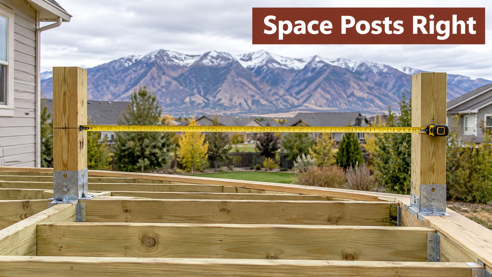
What the layout must carry
A straight level run has different demands from a corner or stair section. A terminal post must hold cable fittings securely. A corner post has to manage a change in direction. An intermediate post limits movement across the run, while the top rail helps tie the assembly together.
Practical rule: A four-foot planning module is a useful starting point, but it isn't a code approval by itself.
For homeowners and contractors comparing deck railing materials, the takeoff should identify every end, corner, stair, and intermediate location before cable quantities are calculated. A separate guide to material-specific railing steps can help organize the installation sequence, but the selected system's tested details and Utah's adopted local requirements remain controlling.
The same logic applies across Salt Lake City, South Jordan, Sandy, Draper, Herriman, Lehi, Ogden, and Provo. Open views are achievable, but wider unsupported runs create more movement and usually require additional support or a system specifically designed for that condition.
The 4-Inch Sphere Rule and Cable Deflection
The 4-inch sphere rule is an opening test, not a recommendation to install cables exactly four inches apart. A cable can bow between posts when pressure is applied, increasing the effective opening at the point where movement is greatest. The measurement therefore needs to account for the cable's installed position and the completed guard's behavior under load.
Cable-railing guidance commonly places vertical cable spacing at approximately 3 inches to 3 1/8 inches, rather than four inches. One engineering guide specifies cable centers no more than 3 inches apart, while another recommends 3 1/8 inches so the cables remain within the sphere limitation when pushed. These figures and the deflection rationale are documented in the cable railing project guide.
Nominal spacing versus clear opening
Cable center-to-center spacing includes the cable diameter. The inspector's concern is the clear opening, including what happens when the cable shifts. A layout that appears acceptable on paper can perform differently if the posts flex, the fittings are installed incorrectly, or the unsupported run is longer than the system allows.
The number of cable runs depends on the guard height and the manufacturer's hole pattern. It shouldn't be guessed from a generic chart because the bottom and top clearances, stair angle, terminal fittings, and approved guard configuration all affect the final count.
Why the historical approach changed
Cable railing was once judged mainly by visible spacing. Modern planning treats it as a tensioned guard system whose performance depends on cable movement, post stiffness, attachment details, and load transfer. That shift explains why a post schedule can't be separated from the cable layout.
A homeowner preparing for a municipal review can also use this guide to navigating deck permit red tape as a planning aid. It doesn't replace confirmation with the local building department. Utah projects remain subject to the adopted local code edition and the building official's interpretation.
Resources describing modern cable railing systems can provide useful product context, but they shouldn't override the selected system's installation manual. The safe sequence is to confirm the code opening requirement, choose the approved vertical spacing, then verify how the post arrangement controls deflection.
Variables That Change Your Maximum Span
There is no universal maximum post spacing for every cable railing assembly. A tested system may permit a different arrangement from another system using the same general cable material. Post construction, cable diameter, cable construction, top-rail stiffness, guard height, tensioning hardware, and attachment details all affect the result.
Start with the post roles
End posts carry the termination hardware and the accumulated tension from the cable runs. They need secure attachment to adequately framed deck structure, not just a decorative connection to fascia or trim.
Corner posts change the direction of the cable path. A corner may require a dedicated corner post, a paired-post arrangement, or a manufacturer-approved fitting strategy. A layout that treats a corner as an ordinary line post can create binding, awkward cable paths, or unsupported openings.
Intermediate posts shorten the cable's unsupported length. Their main job is deflection control, even though they also divide the railing visually. A widely published design benchmark places ordinary metal posts no more than 4 feet apart when cables are spaced near 3 inches; some systems can reach approximately 7 feet only when an intermediate cable stabilizer is added, as described in technical education on cable guard design.
Match the system, not the appearance
Rigid 1x19 cable construction is commonly paired with supports no more than 48 inches apart, while some proprietary systems set a different absolute ceiling and still recommend intermediate posts at roughly four-foot intervals. Metal cable design guidance emphasizes that cable diameter, construction, vertical spacing, post stiffness, guard height, and attachment method work together.
Stabilizers can reduce movement across a longer main-post span, but they don't automatically turn a long opening into a compliant guard. Stairs add another complication because the cable holes follow a slope, the posts may have angled faces, and the terminal hardware must suit that angle.
For a clean view across a Utah deck, the useful target is controlled movement, not the fewest possible posts. The right deck railing for Utah views depends on the system's tested layout and the framing behind it.
Spacing Variables and Layout Decision Matrix
A material takeoff becomes more accurate when the railing is divided into straight runs, corners, stair runs, and transitions before quantities are added. Each category changes the post type, cable path, and fitting count.
The following matrix uses common planning benchmarks. The exact system limit still comes from the selected manufacturer's documentation.
| Deck Scenario | Standard Post Spacing | Required Hardware / Strategy |
|---|---|---|
| Straight level run with rigid metal posts | Approximately 4 feet | End posts, intermediate line posts, continuous top rail, and terminal tensioning hardware |
| Long run where the system permits a wider structural span | System-specific, potentially approximately 7 feet with a stabilizer | Confirm the approved stabilizer, add support as specified, and verify deflection under load |
| Outside or inside corner | Not treated as a normal line-post interval | Dedicated corner post or approved paired-post strategy, with fittings that maintain the cable path |
| Stair transition | System-specific and often tighter than a simple level layout | Angled posts or stair hardware, sloped cable drilling pattern, and separate terminal planning |
| Run with frequent intermediate pickets or stabilizers | Based on the selected support pattern | Use the approved picket or stabilizer detail, then recalculate cable lengths and fitting quantities |
| Any run with uncertain tension or framing | Conservative spacing selected after review | Verify blocking, post anchorage, tensioning method, and local inspection requirements before ordering |
The cable run length affects how much tension reaches the end fittings. Corners can add separate runs rather than one continuous length. Stairs can require different cable cuts because the top and bottom terminations sit at different elevations.
Tensioning also changes the takeoff. Each cable line needs compatible terminal hardware, and a system may use different fittings for through-post, end-post, corner, or stair conditions. Builders looking to find cable railing from Utah Deck Supply should prepare a marked-up plan instead of ordering from total perimeter length alone.
Step-by-Step Calculation for a Standard Run
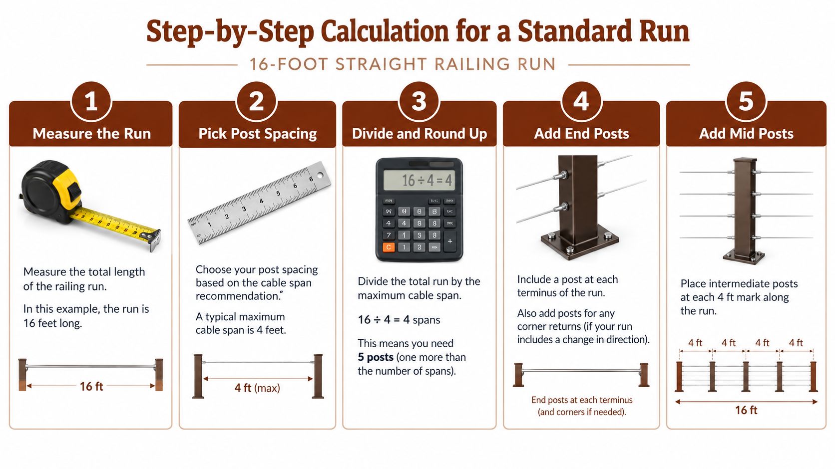
A straight 16-foot railing run provides a useful baseline for estimating a post layout. It doesn't replace a product-specific plan, but it shows how the commonly used four-foot module affects the number of structural supports.
Count the unsupported sections
Measure the run. Record the finished distance between the intended terminal locations. The example run measures 16 feet.
Choose the planning span. Using a 4-foot maximum unsupported span as the starting benchmark creates four equal sections. The selected system may require a shorter interval.
Divide and round up. Divide 16 feet by 4 feet, producing 4 unsupported sections. Four sections require 5 posts when both end posts and the three intermediate locations are counted.
Place the terminals. Mark an end post at each terminus. If either end turns a corner, the corner return needs its own layout and may change the terminal-post count.
Add the intermediate posts. Place intermediate supports at each four-foot division, subject to the actual post dimensions, mounting method, and manufacturer's center-to-center instructions.
Calculate cable lines separately
The post count doesn't determine the cable count. Cable lines are laid out vertically across the guard, with installed centers commonly near 3 inches to 3 1/8 inches. The exact number depends on the guard height, the system's approved hole pattern, and the clearances required at the deck surface and top rail.
A takeoff should therefore have separate lines for:
- Structural posts, divided into end, corner, stair, and intermediate types.
- Cable lengths, measured for each run rather than multiplied from the total perimeter.
- Terminal fittings, matched to each end, corner, and stair condition.
- Stabilizers or support pickets, where the manufacturer's plan calls for them.
- Top-rail and framing connections, which must transfer the guard loads into the deck structure.
The four-foot module in this example creates a starting estimate, not a guaranteed final schedule. If the chosen system has a different maximum span, its manual controls the post count.
Finalizing Your Utah Deck Railing Plan
A reliable order begins with a manufacturer-plan review. The layout should be complete enough that a supplier can distinguish a level end post from a corner post, a stair terminal from a standard terminal, and a cable stabilizer from a structural line post.
Manufacturer-plan checklist
System model: Record the exact cable railing system and configuration. Different models can use different post limits, hole patterns, fitting types, and tensioning procedures.
Terminal hardware: Identify every end fitting, tensioner, swage, turnbuckle, or field-fit component. Compatibility matters because a cable diameter or fitting style that works in one assembly may not be approved in another.
Corner strategy: Mark inside corners, outside corners, and returns. Confirm whether the system uses one corner post, paired posts, or a dedicated corner fitting.
Stair angle: Draw the stair run separately from level guards. Confirm the post orientation, cable hole angle, bottom termination, and handrail arrangement before cutting cable.
Support spacing: List the maximum unsupported span from the system documentation. Add intermediate posts or stabilizers where the run, guard height, top rail, or framing makes movement a concern.
Cable count: Use the approved vertical spacing and guard-height layout. Don't estimate the number of runs from a photograph or a different product line.
Local inspection: Confirm the adopted code edition and local building department requirements in West Jordan, Salt Lake City, Sandy, Lehi, or the project jurisdiction. The 4-inch sphere criterion is a widely used baseline, but the local official and adopted code remain controlling.
Verify the material takeoff
The railing plan should be checked against the deck structure before the order is finalized. Post anchorage, blocking, framing connections, fastener compatibility, corrosion exposure, and the manufacturer's installation requirements all deserve review. A cable system can't compensate for inadequate framing or an incompatible attachment detail.
Utah Deck Supply can help homeowners, contractors, remodelers, and builders compare cable railing with aluminum, steel, composite, and other railing categories while organizing the related deck materials. The same takeoff may include composite, PVC, or wood decking, hidden fasteners, screws, joist tape, flashing, framing hardware, post caps, and deck lighting. Aluminum railing is available, but aluminum deck boards and aluminum deck planks aren't part of the product range.
The Utah Deck Supply showroom in West Jordan gives local customers a place to review railing and decking materials before committing to a takeoff. A marked plan with run lengths, corners, stairs, post types, and the selected system will make a quote more useful and reduce the risk of missing fittings.
The practical decision is simple. Use post spacing to control deflection, use tighter cable spacing to manage the finished opening, and verify every unusual condition against the manufacturer plan and local inspection requirements.
Utah Deck Supply provides composite, PVC, wood decking, cable railing, aluminum railing, hardware, and framing materials for Utah homeowners and contractors planning a complete takeoff. Bring the railing dimensions and system details to the West Jordan showroom, or request a deck materials quote, and call 385-993-5492 for help organizing the post, cable, fitting, and support list.